Blog 3
During the weeks of October 28 - 11, we constructed and assembled the CAD components of the arm attachments, selected materials, and completed our initial engineering calculations. Additionally, we scheduled meetings with the clients in order to present our design ideas, gather feedback, and get approval for items for purchase. After last week’s meeting, the client informed us that they would like to add another project scope. The client wants to utilize a second BIKE platform to spray a developer. This incorporates a third action into the team's design. In order to complete the new project scope, we have divided the work into 3 tasks: CAD design for the developer can, building the enclosure for the first BIKE robot, and completing any additional engineering analysis for the developer can assembly.
The team expects to finish the engineering analysis for the project during the timeframe of November 11 through November 25. Such calculations include determining the flow rate of the fluids, the required power input of the pumps, expected electronic run time off a battery pack, finite element analysis, and safety factor on the arm attachment. Also, the team is expected to finalize the CAD design of the robotic arm assembly with all of its components. Given that the team is still on schedule, the team anticipates sending and 3D printing the CAD files during the winter break. This will give the team a head start on Milestone 4.
The team foresees the attachment meant to continuously shake the developer can to be a slight obstacle due to it being a new task. However, the team plans on using the same horizontal arm attachment while utilizing a fan, motor, and pivot arm assembly to remotely shake the can. After completing the additional CAD design for the new assembly, the team will present the ideas in next week’s meeting with the client for final approval. In case the design is not approved by the client, the team has built in another week of buffer time to account for delays in work, while still being on time for the design report submission.
Below are the updated CAD designs based on the additional scopes. Since the client preferred the horizontal iteration, our future work will be geared towards that solution. Figure 1 is our finalized design concept for BIKE 1 with all of the enclosures for the material components. Figure 2 is the updated design for BIKE 2 with the develop application. Figures 3-5 are our updated calculations, taking into consideration the developer can.
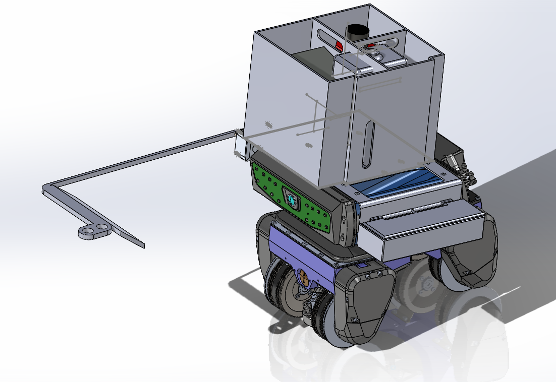
Figure 1: Dye Penetrant Arm Attachments
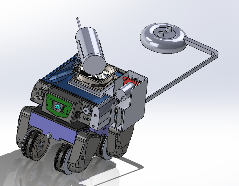
Figure 2: Developer Can Attachments
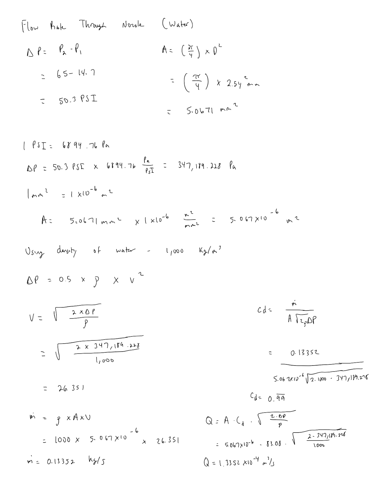
Figure 3: Fluid Flow Rate of Water
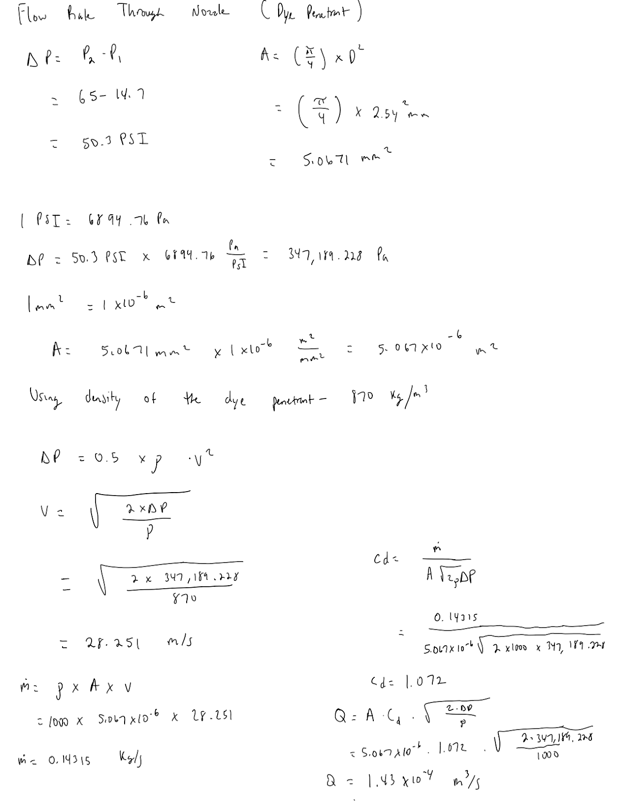
Figure 4: Fluid Flow Rate of Dye Penetrant
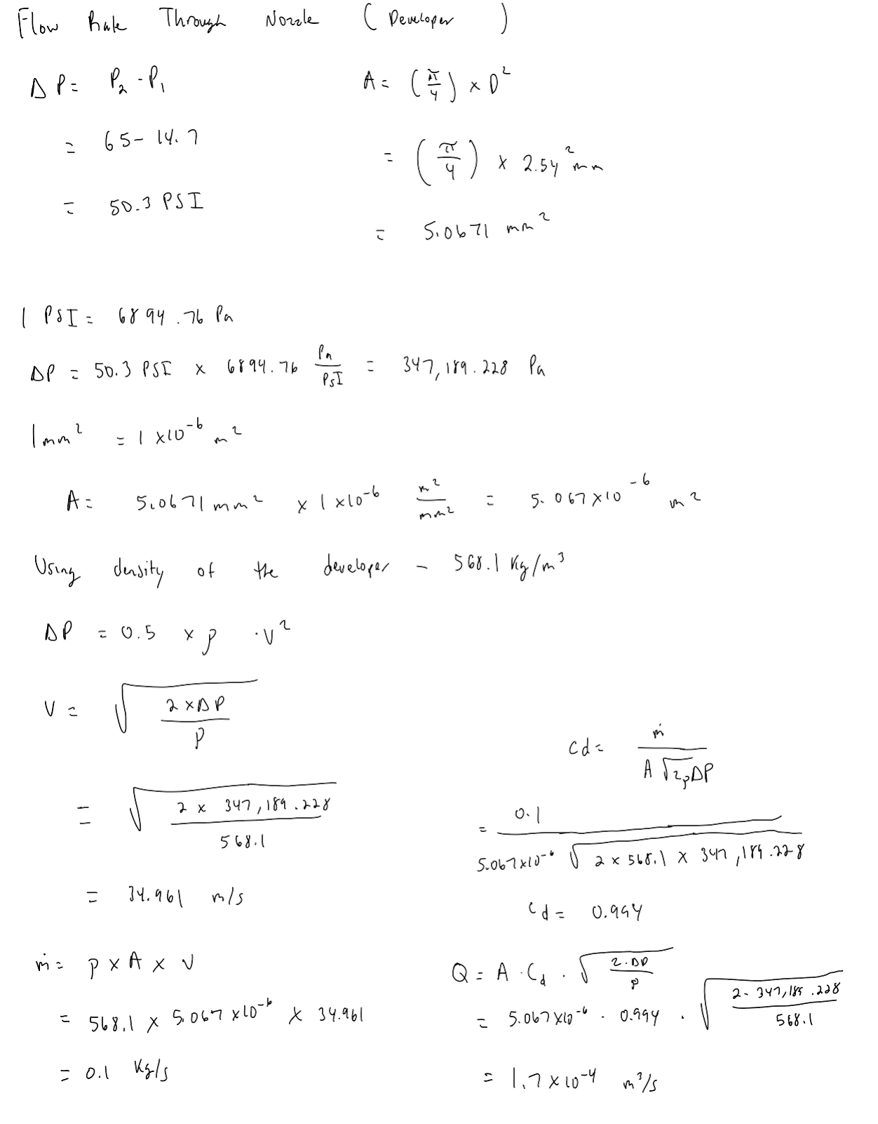
Figure 5: Fluid Flow Rate of Developer
Comments
Post a Comment