Blog #4
For the work period of November 11th through 25th, the team has redone several engineering analyses to accommodate the sponsor company’s additional project scopes and part changes. The sponsor company has stated that they would prefer if the team is able to work with an additional robot to spray the developer during the dye penetrant test. Thus, the team has utilized the same design used in the first robot (Figure 1) and updated it to use the developer spray can (Figure 2). The analysis completed includes static calculations using free body diagrams, flow rate calculations on the nozzle, power calculations between the components, and estimated run time calculations. Several simulations were done in SolidWorks in areas of stress, strain, and flow rate to emulate what the nozzle and arm attachment would experience when using the product. Currently, the team is finalizing the accuracy of the CAD model to calculate the factor of safety with the arm attachments, as well as analyzing gravitational effect on the attached components within the container designed to hold each item. Additionally, the team is finalizing the specifications sheet in accordance with the changes made to components and requests from the stakeholders.
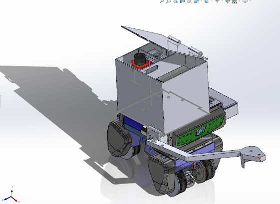
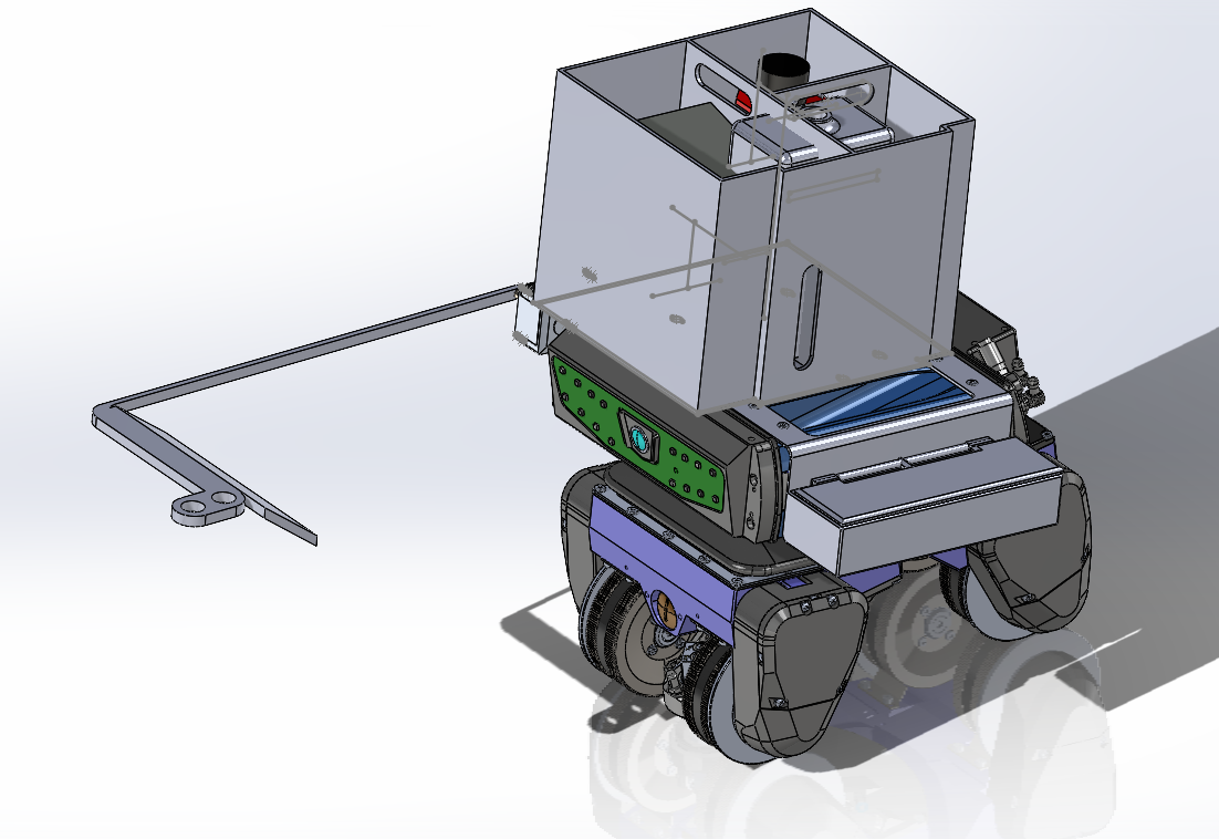
Figure 1: Dye Penetrant Attachment with Components
Figures 1 and 2 represent the final designs for dye penetrant attachments. Figure 1 is an illustration of the robot that will be applying dye penetrant and cleaning with water spray. Key design features include the routing of dye penetrant from the container (16oz) towards the 12V pump, which will direct the penetrant at a rate of 1.8 L/Min towards the nozzle and spray in a coarse pattern. Similarly, the robot will also be spraying water by rerouting the built in water source through the 12V pump and nozzle. To ensure maneuverability, the tubes will be longer to ensure plenty of slack. The arm attachment will be able to move up and down with the use of a worm geared 12V DC motor. All of the said components will be wired to a bluetooth board and motor control attached on the left hand side of the robot. Furthermore, all the components will be enclosed in a perfect fit container to accommodate for the mobility purposes in tank floors.
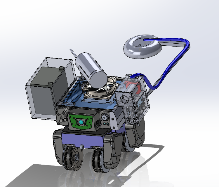
Figure 2: Developer Can Attachment with Components
The second figure illustrates the developer spray attachment robot, which will spray a white developer substance. The design incorporates a can holder, fan, pump, and bluetooth board. The fan assembly will provide circular movement to the developer can to agitate and properly mix the fluid before spraying. Similar to the first robot design, the pump, nozzle, and arm attachment will work together to spray onto the surface area. Team will also ensure proper spacing for each component and enclose the entire assembly. Both robot attachment designs include a splash guard and arm extends out ~12 inches to ensure that none of the liquid being sprayed will obstruct the front camera.
The key analytical results the team has includes flow rate calculations demonstrating the calculated flow occurring at the nozzle, estimated run time for all components operating simultaneously at max voltage, finite element analysis, and flow rate simulations. These key analyses address the main objectives and constraints set earlier in the semester by defining/simulating probable outcomes of using certain products over others. For example, the
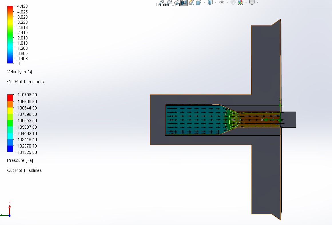
Figure 3: Flow Rate Velocity Within The Nozzle
simulations indicated that the pressure expected at the nozzle tip is 15 psi, which falls under the 65 psi threshold set by stakeholders. Similarly, when conducting finite element analysis based on expected pressure, there was only minor stress and strain observed at the tip of the arm attachment. Furthermore, factor of safety (FOS) obtained from simulations indicated that the minimum and maximum (1 and 6 respectively) are within the allowable limits for the given component. Looking at the overall attachment and expectations for run time, early indications point towards a runtime of 20 minutes at highest operation capacity. This proves the robot arm attachment will be able to complete the tasks within the allocated procedure time.
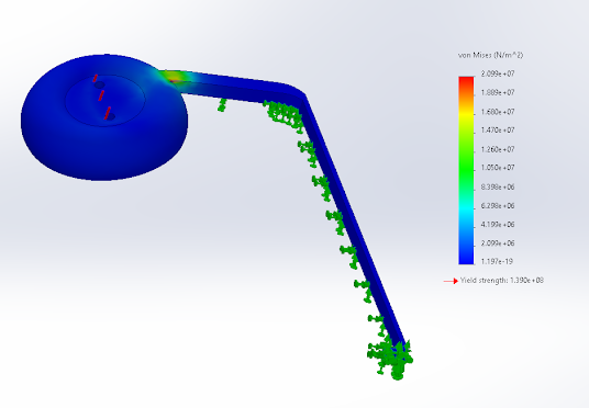
Figure 4: FEA Analysis of Arm Attachment
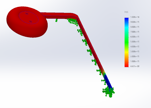
Figure 5: FOS Analysis of Arm Attachment
Looking forward to Capstone 2, the team plans on getting a head start on Milestone 4 dates by utilizing the sponsor company’s resources to 3D print and build/buy the parts necessary to construct the project. Throughout the winter break the team will work on having the project assembled and trialed as much as possible to be ready for validation.
Comments
Post a Comment