Blog #8
Over the period of March 23-April 13th, the team has made progress in getting the final fabricated items and test fitting the components to the BIKE robot. Having success with the assembly, the team did several test runs with the sponsor company on demo day to ensure that the proposed project results were achievable. The demo test also revealed areas that could improve, especially in regards to the developer option attachment. The team did further validation on the pressure of the fluid exiting the pump, strain gauge, and load cell testing.
For validation, the team conducted a new pressure gauge test with a custom made fitting that attaches directly to the peristaltic pump. This fitting allows for direct connection between the pressure gauge and a 10mm tube. The custom piece was made to remove the 7mm to 10mm adapter that was initially needed and thus confirm any differences in test data. Upon several runs with the pressure gauge testing, the data revealed the same results as the ones with the adapter. All of the pressure gauge testing confirmed that the device will operate under the given constraints of 0-65 psi range for fluid flow. For the strain gauge testing, the team used a 350 ohm strain gauge along with a D4 bridge quarter connection. The strain gauge was placed at the midpoint where most of the strain was expected on the arm. With the contraption, several weights were added to the nozzle connection area to see when the device would fail. From the data obtained, the arm failed at a weight of 4-5 lbs at the motor shaft connection. These tests confirmed that the team can work with various nozzle types and tube lengths within the weight limits. Similarly, load cell testing was used to understand the amount of tension the motor arm attachment is able to create. The tension and cantilever load determines if the arm can move easily during operation. Lastly, the team used a thermometer to track fluid temperatures so it does not exceed the sponsor’s constraints and negatively impact the dye penetrant testing. The results yielded an average temperature of 72 degrees fahrenheit, which is within the bounds.
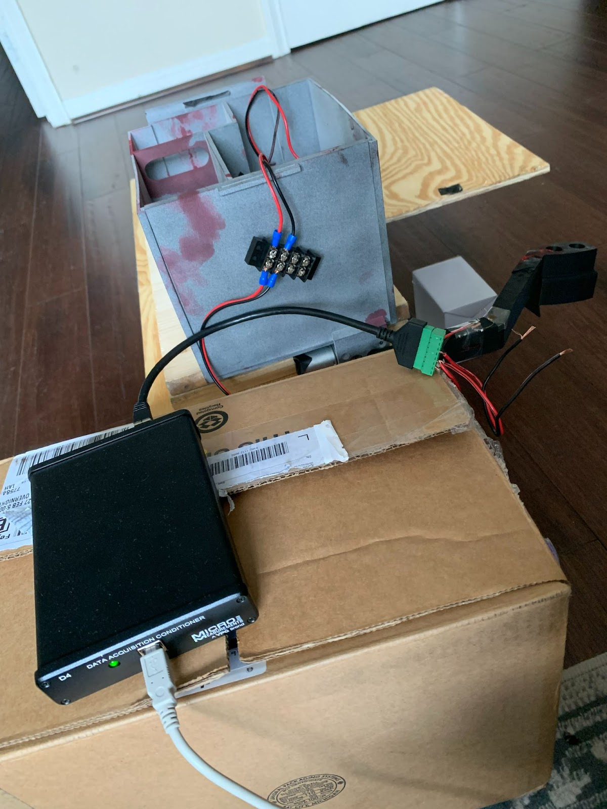
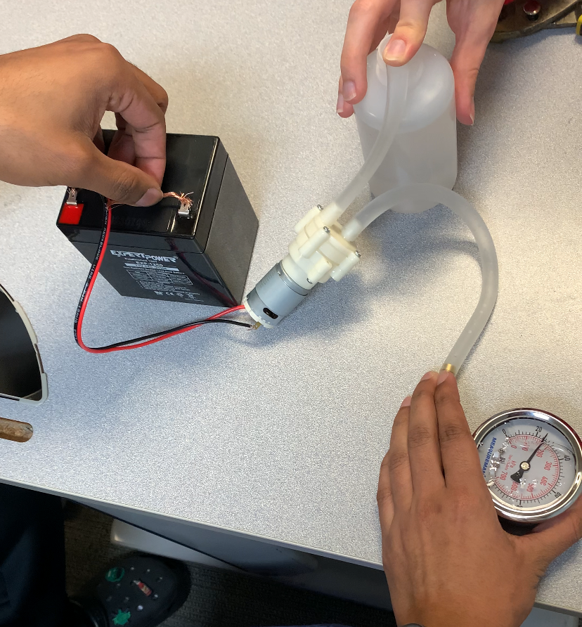
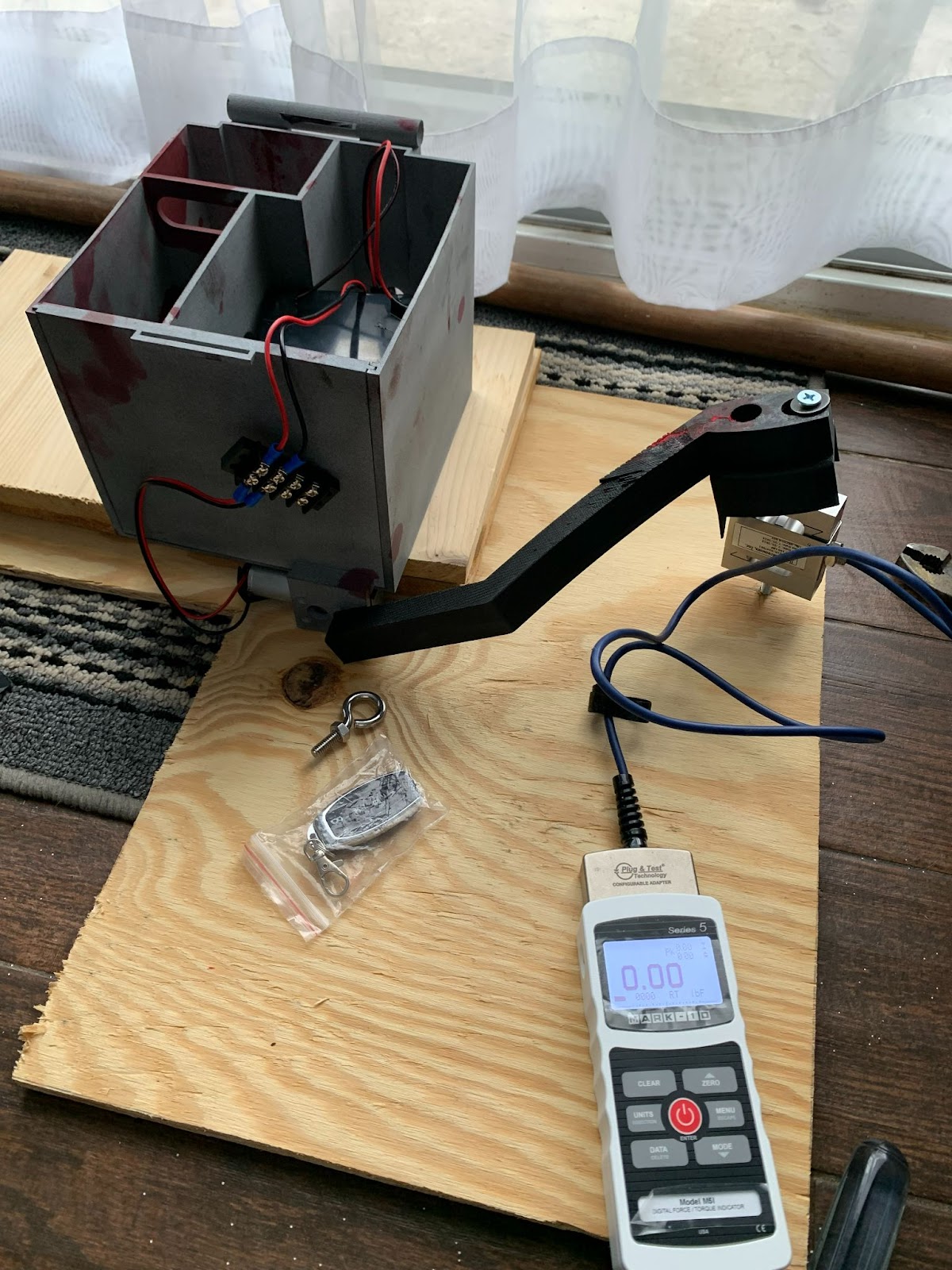
Figure 1-3: Strain Gauge, Pressure Gauge, and Load Cell Testing
With the remaining time the only improvements that need to be made for the project is a new fabricated box to hold all the components. The current box utilized during demo runs had a few defects when fabricating and thus prevented the team from properly closing the lid. The final fabricated CAD has been sent to the sponsor company and will be printed by April 15th. Afterwards, the team will perform a final demo at the sponsor company that same week. During this time, the team will perform the rest of the validations using the multimeter function to test the voltage distribution among components, weight of the project arm attachments, and redo strain gauge testing if necessary to get further detailed results. Additionally, the team plans on researching and recommending possible alternatives to adjusting the speed of the motor.
Finally, this is our current draft for the technical poster. The team will finalize figures, text, and overall layout by the end of next week to submit.
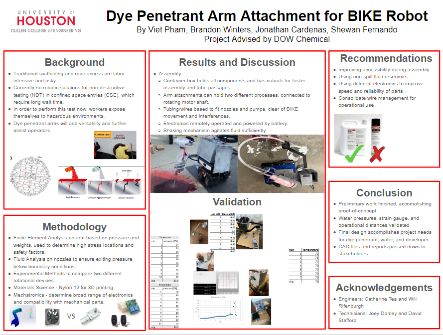
Figure 4: Technical Poster Draft
Comments
Post a Comment