Blog #5
For the work period of December 11-February 3, the team has met with stakeholders to make final adjustments to the design before sending the CADs’ for fabrication. The team redid the stress analysis to simulate a better representation of the load applied to the arm attachment. Currently the team is fabricating fittings for the nozzle and tube connection to allow a seamless attachment for fluid flow. The team is also purchasing a pressure gauge and T-fittings for further project validation.


For the work period of February 4 - February 17, the team plans to assemble all the fabricated components, confirm that the parts work together within the design, and proceed with validating the goals set at the beginning of semester 1. Major milestones the team hopes to achieve include assembly of all the components, validation of the nozzle pressure, distance of the spray, fluid temperatures, and battery life of electronics to cross reference with real time operations.
During the next two weeks, the team plans on improving the parts that have been 3D printed by the client company. Based on feedback, there were some design flaws that worked in the CAD model, but were structurally weak during the manufacturing process. Additionally, the team also anticipates some incohesiveness between parts produced and purchased materials, which the team may possibly have to modify to fit correctly. Hand and machine tools will be used to tweak certain components to make sure the assembly works together. To account for delays in project completion, the team procured parts earlier to allocate appropriate buffer times. As of this moment, the team is ahead of schedule by approximately 1-2 weeks.

Figure 1: Hinges Before Fabrication.

Figure 2: Hinge Update After Fabrication
Figures 1 and 2 illustrate the improvements to the hinges following fabrication issues. For the updates, the hinges are thicker and reinforced to allow improved connection between the lid and container.

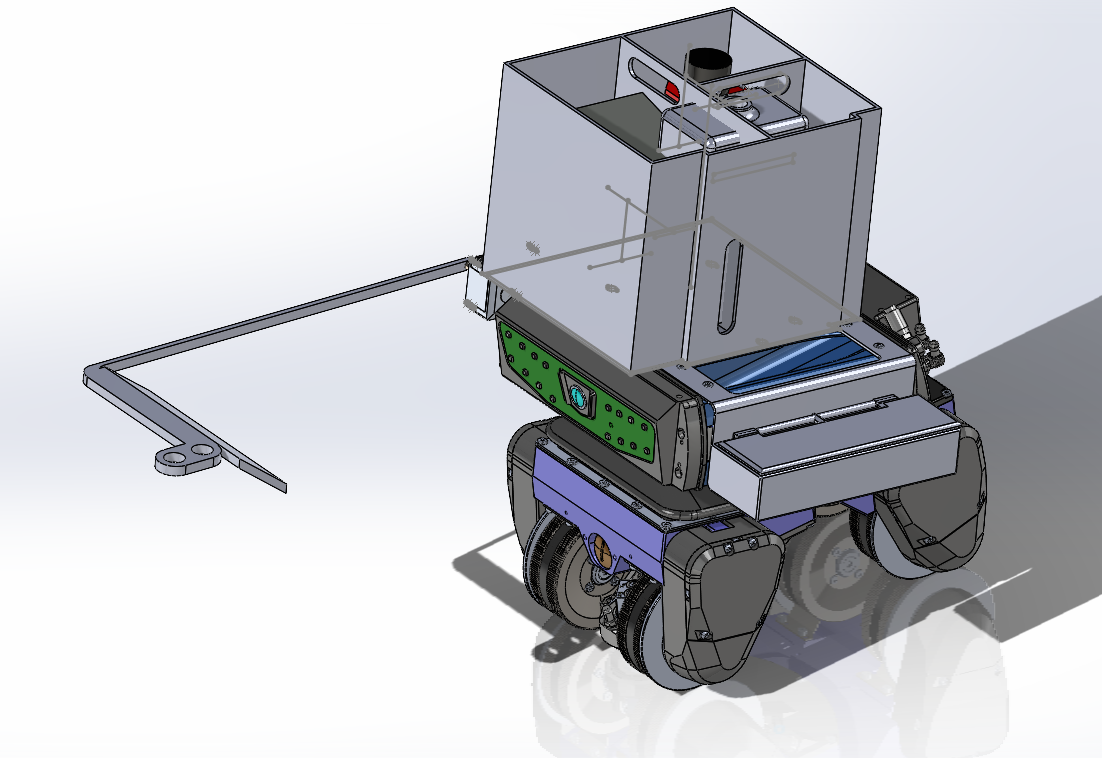
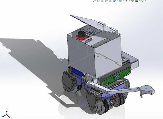
Figure 3: Fabricated Arm Components and Electronics Bracket.
Figure 3 is showcasing the fabricated arm attachments for horizontal concept and developer option, electronics bracket box, and can shaker. All the fabricated pieces are printed using industrial 3D printer with nylon material. The materials were assembled together to confirm their compatability such as the electronic box and lid as well as slide in mechanisms.


Figure 4: New Stress Analysis for Accurate Depiction of Loads
The last figure is a representation of stress analysis done on the arm attachment to simulate actual loads and conditions it will undergo when operating on the robot. The updates were made to a small square on the bottom side of the arm where it is subjected a fixed load. The fixed load is positioned at the arm location to maintain the height requirements for adaquet spray region.
Comments
Post a Comment