Blog #7
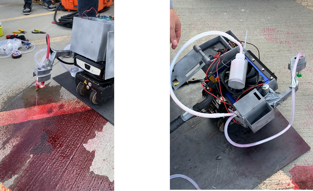
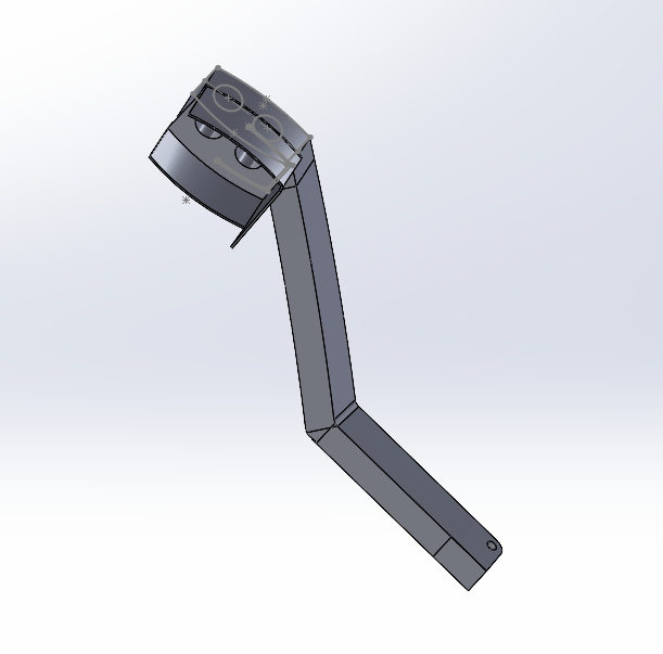
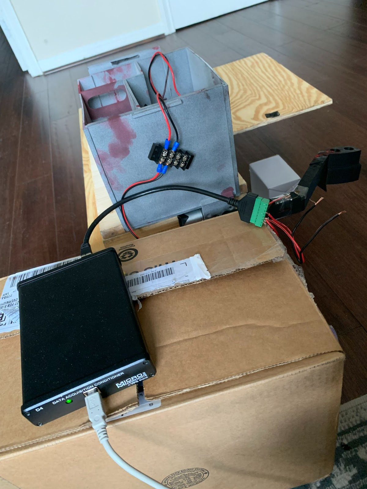
From March 9 - 23, the team updated the CAD models according to the first prototype testing. After the test, there were some flaws in the 3D printed materials that made accessibility an issue. For example, the screw holes where the box fit onto the top of the robot made it hard to mount. This made assembly a challenge and also certain materials hard to reach. To mitigate this, there are holes cut into the box to ensure they can reach for the next test. The team has already submitted the final iteration to test. The parts are currently being printed by the stakeholders’ technicians. Finally, because the motor spins at a high rate, the team is utilizing a stopper to ensure the arm attachment stops at a 90 degree angle from the floor. The developer assembly has also been updated to fit a motor instead of fan, which will allow greater torque output.
The team plans to have the final iteration of prints by the end of next week. Afterwards, they will focus on refining the materials with electronic components to make sure everything still fits as intended. The team will then be prepared to set up the final assembly for demonstration April 1st in front of both the professor and stakeholders. Additionally, the team will start the process for the final validations. The team will then be able to finish their last two milestones, which consists of preparing and compiling all reports and parts for the robotic engineers to keep for record and future work. For the rest of April, they will focus on preparing the technical report and presentation based on the capstone work completed.
The team foresees the connection between the motor pin and the arm to be an issue. The pin stripped the fitting of the arm, so the next iteration of print will be made in plastic to bypass this issue. Should this still be a problem, there are plans to secure the arm to the shaft using a clevis pin attachment. The fan attachment was another obstacle. Because it did not provide enough torque to spin the developer, the team will replace the fan with a motor instead, which will allow enough spin to agitate the fluid.
The following figures below showcase the two assemblies designed and tested.
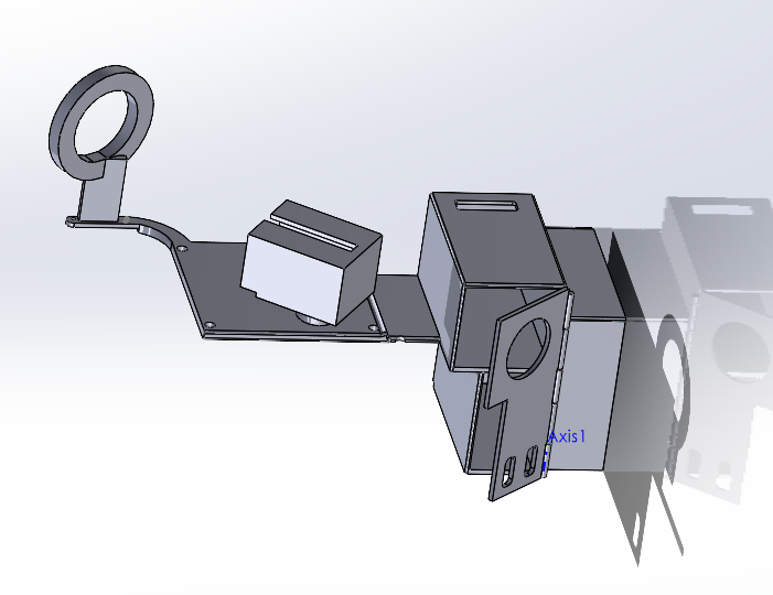
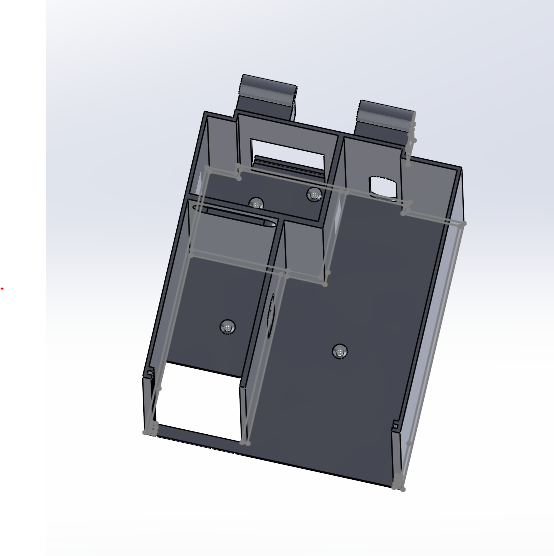
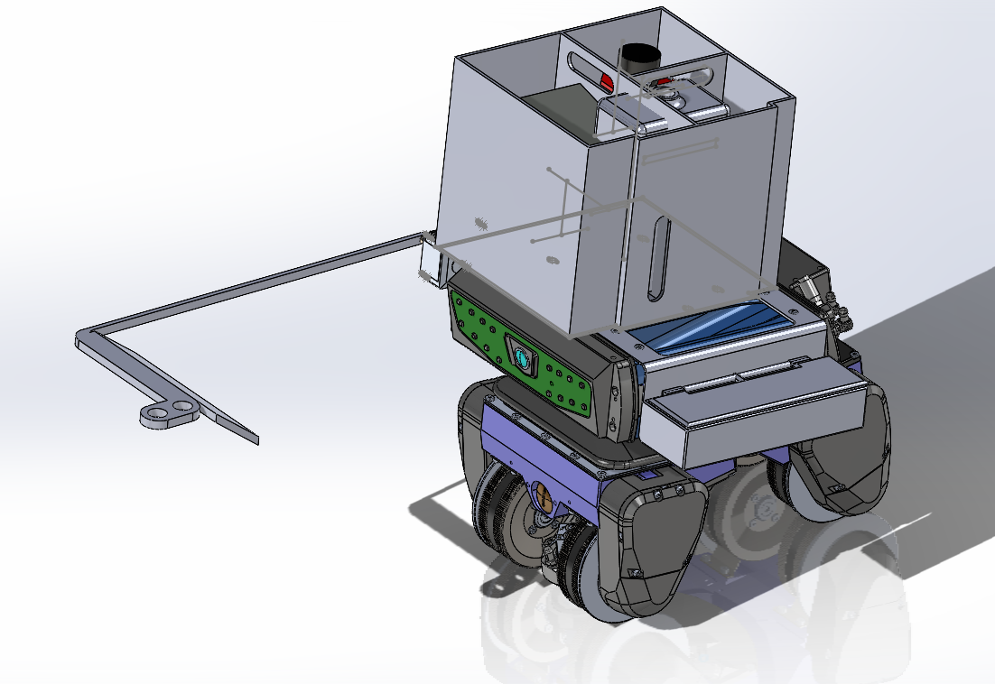
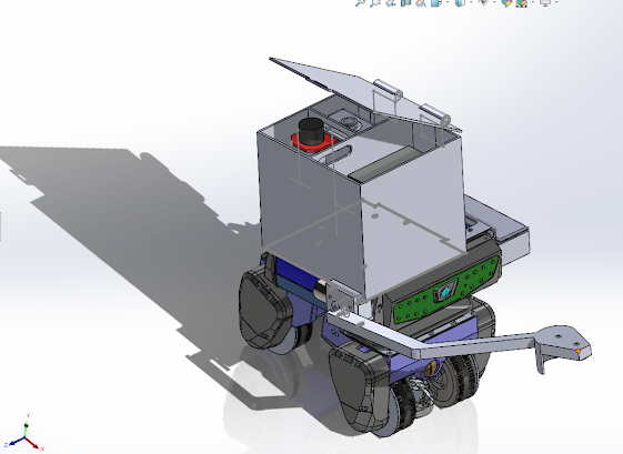
Additionally, the below CADs are the updated developer and dye penetrant assemblies respectively. This will provide better capability to shake the developer can. The stabilizer ring was enlarged to allow better rotation. The box assembly below has also been updated. As shown, cuts are extruded for easier hand access.
The splash shield has also been extended on the arm, to protect and cover both the robot and the materials.
The splash shield has also been extended on the arm, to protect and cover both the robot and the materials.
Comments
Post a Comment