Posts

Blog #8

Image
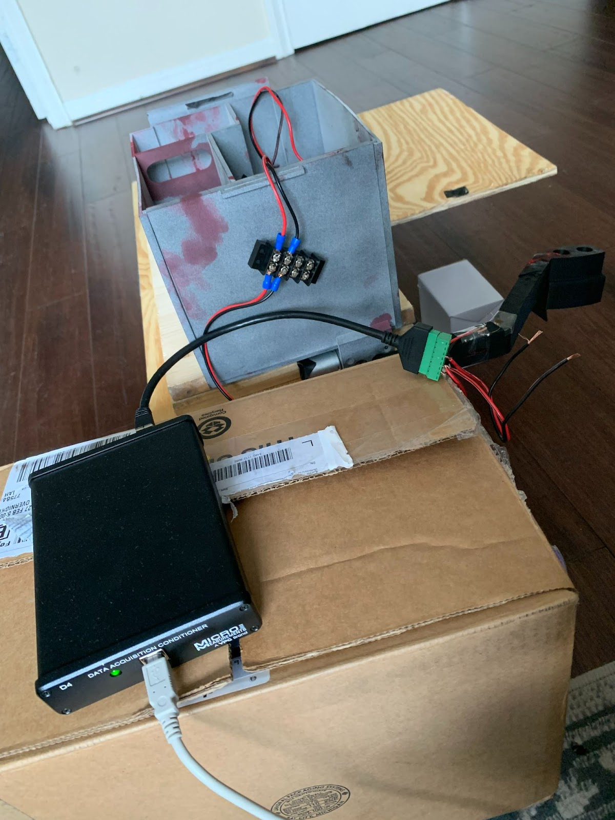
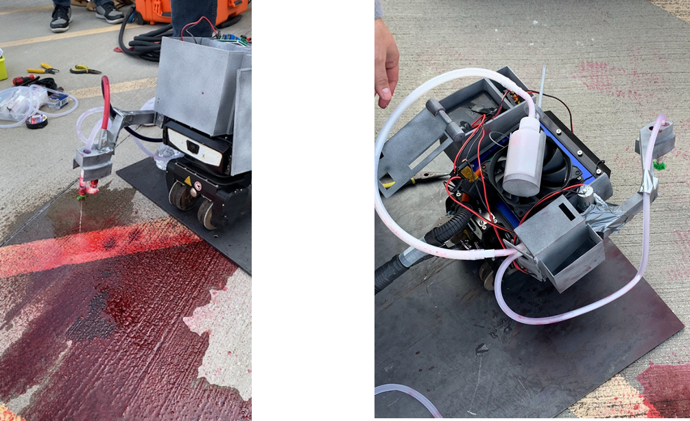
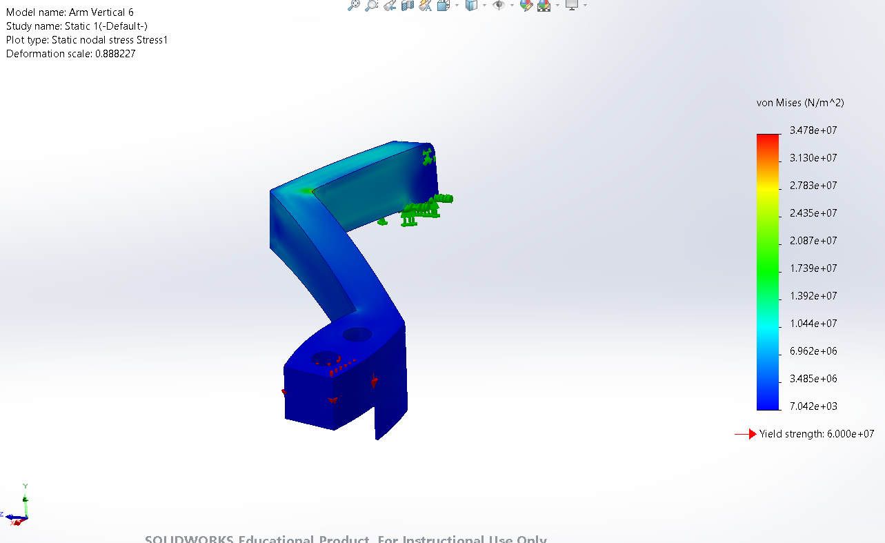
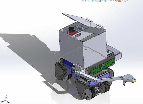
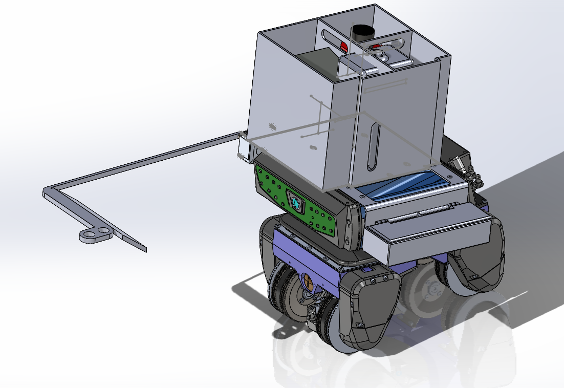
Over the period of March 23-April 13th, the team has made progress in getting the final fabricated items and test fitting the components to the BIKE robot. Having success with the assembly, the team did several test runs with the sponsor company on demo day to ensure that the proposed project results were achievable. The demo test also revealed areas that could improve, especially in regards to the developer option attachment. The team did further validation on the pressure of the fluid exiting the pump, strain gauge, and load cell testing. For validation, the team conducted a new pressure gauge test with a custom made fitting that attaches directly to the peristaltic pump. This fitting allows for direct connection between the pressure gauge and a 10mm tube. The custom piece was made to remove the 7mm to 10mm adapter that was initially needed and thus confirm any differences in test data. Upon several runs with the pressure gauge testing, the data revealed the same results as the ones

Blog #7

Image
     From March 9 - 23, the team updated the CAD models according to the first prototype testing. After the test, there were some flaws in the 3D printed materials that made accessibility an issue. For example, the screw holes where the box fit onto the top of the robot made it hard to mount. This made assembly a challenge and also certain materials hard to reach. To mitigate this, there are holes cut into the box to ensure they can reach for the next test. The team has already submitted the final iteration to test.  The parts are currently being printed by the stakeholders’ technicians. Finally, because the motor spins at a high rate, the team is utilizing a stopper to ensure the arm attachment stops at a 90 degree angle from the floor. The developer assembly has also been updated to fit a motor instead of fan, which will allow greater torque output.      The team plans to have the final iteration of prints by the end of next week. Afterwards, they will focus on refining the material

Blog #6

Image
     For the work period of February 4 - 17th, the team has made design updates to the arm to reduce the amount of moment it’s experiencing by elongating the height while decreasing the width. The team made changes to the hinges based on feedback from the sponsors after the initial fabrication experienced errors in printing. The updated hinge design was applied to the developer box, both electronics boxes, and horizontal attachment component box. After fitting the components to the box, the team decided to increase the height of the components box (Figure 1) to better hold the peristaltic pump without causing the tubing to bend. Furthermore, the team started the validation process for peristaltic pump exit pressure and pressure near nozzle.      For the work period of February 17- March 9, the team plans on receiving the new fabricated pieces and test fitting all components, completing all water pressure validation, strain gauge testing for arm attachments, and completion time. The tea

Blog #5

Image
     For the work period of December 11-February 3, the team has met with stakeholders to make final adjustments to the design before sending the CADs’ for fabrication. The team redid the stress analysis to simulate a better representation of the load applied to the arm attachment. Currently the team is fabricating fittings for the nozzle and tube connection to allow a seamless attachment for fluid flow. The team is also purchasing a pressure gauge and T-fittings for further project validation.       For the work period of February 4 - February 17, the team plans to assemble all the fabricated components, confirm that the parts work together within the design, and proceed with validating the goals set at the beginning of semester 1. Major milestones the team hopes to achieve include assembly of all the components, validation of the nozzle pressure, distance of the spray, fluid temperatures, and battery life of electronics to cross reference with real time operations.       During th

Blog #4

Image
       For the work period of November 11th through 25th, the team has redone several engineering analyses to accommodate the sponsor company’s additional project scopes and part changes. The sponsor company has stated that they would prefer if the team is able to work with an additional robot to spray the developer during the dye penetrant test. Thus, the team has utilized the same design used in the first robot (Figure 1) and updated it to use the developer spray can (Figure 2). The analysis completed includes static calculations using free body diagrams, flow rate calculations on the nozzle, power calculations between the components, and estimated run time calculations. Several simulations were done in SolidWorks in areas of stress, strain, and flow rate to emulate what the nozzle and arm attachment would experience when using the product. Currently, the team is finalizing the accuracy of the CAD model to calculate the factor of safety with the arm attachments, as well as analyzing

Blog 3

Image
During the weeks of October 28 - 11, we constructed and assembled the CAD components of the arm attachments, selected materials, and completed our initial engineering calculations. Additionally, we scheduled meetings with the clients in order to present our design ideas, gather feedback, and get approval for items for purchase. After last week’s meeting, the client informed us that they would like to add another project scope. The client wants to utilize a second BIKE platform to spray a developer. This incorporates a third action into the team's design. In order to complete the new project scope, we have divided the work into 3 tasks: CAD design for the developer can, building the enclosure for the first BIKE robot, and completing any additional engineering analysis for the developer can assembly.  The team expects to finish the engineering analysis for the project during the timeframe of November 11 through November 25. Such calculations include determining the flow rate of the

Blog # 2

Image
  This past week, the team met with the robotics engineers and NDT Subject Matter Expert (SME) at DOW Chemical to introduce ourselves and get more clarity on stakeholder needs. They looked over the quantifiable measurements, but wanted to include another physical requirement for the attachments: being able to spray dye penetrant on welded seams, which occur at various curvatures. Based on that added scope, we have refined our technical problem statement with the following physical constraints:  Statement of the Goal The goal of the project is for a robotic arm attachment to perform dye penetrant testing by executing a 3 step procedure: apply water-washable dye penetrant thoroughly to cracks or weld seams, rinse with water pressure less than 30 psi at a distance of 6-12 inches from the surface, and wiping excess penetrant without removing the penetrant from the crack. Constraints  Size of BIKE Robot (9.5” L x 7.5” W x 8.5” H) Tubing/mechanics must operate along tether: 70’ Be able to op